md image link - cdn.mkaidevops.xyz 연결 |
||
|---|---|---|
| .. | ||
| Lesson_3_Button_control_LED.ino | ||
| README.md | ||
README.md
3. Button control LED
3.1.Overview
This section focuses on learning how to use buttons to control LEDs to implement the delay control function.
3.2. Working principle
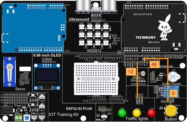
The key signal pin S has a pull-up resistor by default, so it is high level and changes to low level when the key is pressed. At this time, the input of pin 46 of the main control board is low level. By judging the pin status as a condition, the LED pin level is flipped, thereby controlling the LED to turn on and off.
3.2.1.LED
LED(Light Emitting Diode), which converts electrical energy into light energy, also has one-way conductivity and a reverse breakdown voltage of about 5v. Its forward volt-ampere characteristic curve is very steep. In the development board, the negative electrodes of the LEDs are all common to the ground. When the signal pin is set to high level , the LED is on, and when it is set to low level , the LED is turned off.
3.3.Connect the lines
3.4.Upload code
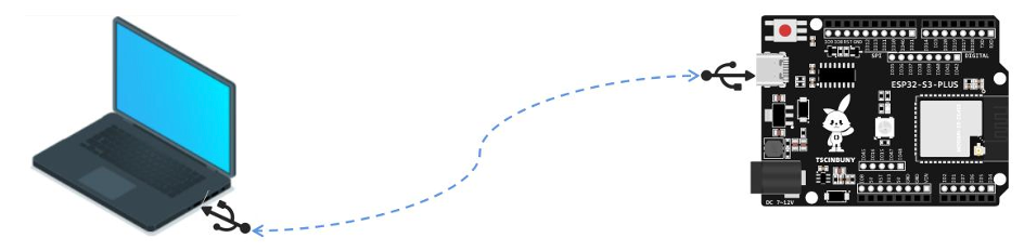
3.4.1. Connect the main control board to the computer with a USB cable
3.4.2. Open the program file (path: 2_ESP32_S3_PLUS \ Lesson_3_Button_control_LED )
Also select the board type as ESP32S3 Dev Module, and select the COM number that is newly displayed when the USB is
plugged in. In this case, it is COM29, but the actual COM number will be different for everyone. Click "Upload" to start compiling and uploading the program to the main control board. Wait for the program upload to complete .
Press the button to light up LED2, press it again to turn off LED2 , and repeat the above effect.
3.5. Code analysis
First define the led pin , button pin and define two variables
#define LED 13
#define button 8

int key_ok = 0;  //Define the data variables needed for the project
int LED_en = 0;
Set the button pin as input and the LED pin as output
void setup() {
  pinMode(button, INPUT);  //Define the operation mode of the pin
  pinMode(LED, OUTPUT);
}
Obtain the button status within the loop structure, use the if...else... statement to determine whether the button is pressed or released, implement the debounce function for the button status variable key_ok, and reverse the LED_en state when the button is released, thus affecting the LED Write high and low levels to make the LED turn on or off.
void loop() {
 // Determine if a button has been pressed and read the button level
 if (digitalRead(button)) {
   if (key_ok)  // Determine if the button is pressed
   {
     key_ok = 0;
     if (LED_en) LED_en = 0;  // Determines whether the last flag bit is established
     else LED_en = 1;
   }
 } else {
   delay(20);
   if (!digitalRead(button)) key_ok = 1;
 }

 // When the key is pressed, the level of the LED light output pin is reversed
 if (LED_en) digitalWrite(LED, HIGH);
 else digitalWrite(LED, LOW);
}