image ling cdn |
||
|---|---|---|
| .. | ||
| Lesson_5_Traffic_light.ino | ||
| README.md | ||
README.md
5. Traffic lights
5.1 Overview
In this section, you will learn to light multiple LEDs and control the green, yellow, and red lights to light up at intervals through a delay function to achieve the effect of a traffic light.
5.2. Working principle
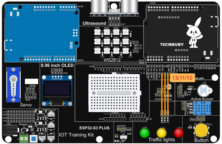
There are three colors of traffic lights, green light, yellow light and red light. The pins connected to the main control board are 13/11/10. By controlling the high level of the three pins, the corresponding lights can be lit. A single light cycle is as follows: first let the green light be on for a period of time, which means that the traffic is in a passable state, then flash a reminder before the green light ends and switch to the yellow light, then switch to the yellow light, and wait for a short period of time before switching to the yellow light. Switch to red light. The red light also waits for a period of time, indicating that traffic is prohibited from passing, and flashes as a reminder before the red light ends and is ready to switch to the green light. So the single-cycle process is roughly as follows: Leave the green light on for five seconds , the green light flashing every 500 milliseconds, the yellow light on for 1 second,
the red light on for 5 seconds, the red light flashing every 500 milliseconds, and so on.
5.3 Connection lines
5.4 Upload code
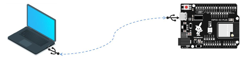
5.4.1 Connect the main control board to the computer using a USB cable
5.4.2 Open the program file (path: 2_ESP32_S3_PLUS\ Lesson_5_Traffic_light )
Also select the board type as ESP32S3 Dev Module and select the COM number newly displayed when the USB is plugged
in . Then click "Upload" to start compiling and uploading the program to the main control board.
5.5 Code analysis
Define three LED pins
#define Green 13   // Define the green light pin
#define Yellow 11  // Define the yellow light pin
#define red 10     // Define the red light pin
Set pin as output
void setup() {
  // Define the pin as the output working mode
  pinMode(Green, OUTPUT);
  pinMode(Yellow, OUTPUT);
  pinMode(red, OUTPUT);
}
The loop function executes a single light cycle.
The red light first lights up for 5 seconds and then flashes every 500 milliseconds.
 void loop() {
  digitalWrite(Green, HIGH);  // Turn on the green light
  digitalWrite(Yellow, LOW);  // Put out the yellow light
  digitalWrite(red, LOW);     // Turn off the red light
  delay(5000);                // Turn on the green light for five seconds

  // The green light flashes every 500 milliseconds
  digitalWrite(Green, HIGH);
  delay(500);
  digitalWrite(Green, LOW);
  delay(500);
  digitalWrite(Green, HIGH);
  delay(500);
  digitalWrite(Green, LOW);
  delay(500);
  digitalWrite(Green, HIGH);
  delay(500);
Yellow light on for 1 second
 // The yellow light is on for 1 second
  digitalWrite(Green, LOW);
  digitalWrite(Yellow, HIGH);
  digitalWrite(red, LOW);
  delay(1200);
Finally, the red light turns on for 5 seconds and then flashes every 500 milliseconds
// The red light stays on for 5 seconds
  digitalWrite(Green, LOW);
  digitalWrite(Yellow, LOW);
  digitalWrite(red, HIGH);
  delay(5000);

// The red light flashes every 500 milliseconds
  digitalWrite(red, HIGH);
  delay(500);
  digitalWrite(red, LOW);
  delay(500);
  digitalWrite(red, HIGH);
  delay(500);
  digitalWrite(red, LOW);
  delay(500);
  digitalWrite(red, HIGH);
  delay(500);